
HVAC Design: Principles, Sizing, BIM & Energy Efficiency Tools
Discover how to design an HVAC system with load calculations, ventilation, air and water networks, BIM, simulation, and sizing
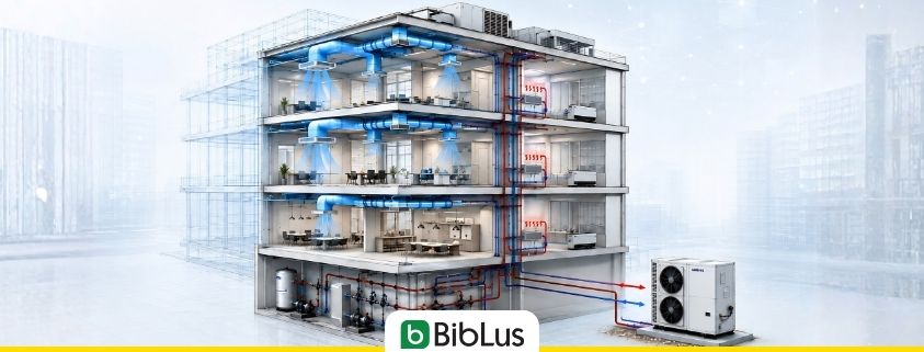
The design of HVAC systems represents a field of applied engineering that integrates principles of thermodynamics, heat transfer, and fluid mechanics to define systems capable of ensuring thermal comfort, air quality, and energy control in buildings.
Heating, ventilation, and air conditioning systems encompass the set of solutions that allow for effective management of internal environmental conditions, with the goal of ensuring comfortable, healthy spaces that align with usage requirements.
The design of HVAC systems constitutes one of the areas of thermotechnical design and specifically relates to the definition, sizing, and control of the systems necessary to manage temperature, humidity, ventilation, and air quality in indoor environments.
If you want to explore what HVAC systems are, how they function, and what the main types are, you can consult the dedicated guide. In this article, we will focus primarily on the design and sizing process.
Indeed, HVAC design is not limited to the selection of equipment. It requires correlating thermal loads, ventilation flows, building characteristics, air and water networks, control systems, and energy performance.
To assess how these variables impact the overall behavior of the building, and to compare different design solutions before implementation, it may be useful to resort to a building energy simulation tool to integrate into the workflow alongside calculation tools, BIM modeling, and sizing of systems.
Contents
- What is HVAC design and why is it important?
- How to design an HVAC system?
- Main Areas of Application for HVAC Design
- HVAC Design for Energy Efficiency and Environmental Sustainability
- Ventilation and Air Quality in HVAC Design
- Sizing of HVAC Duct and Hydronic Networks
- BIM and Coordination in HVAC Design
- Regulation, BACS and Building Automation in HVAC Systems
- Verification, Balancing, and Commissioning of HVAC Systems
- Technical Skills of the HVAC Designer
- What Tools Are Needed for HVAC Design?
- FAQ – HVAC Design
What is HVAC design and why is it important?
HVAC design (Heating, Ventilation, and Air Conditioning) refers to all activities necessary to define, size, and integrate the systems that regulate thermal and hygienic conditions and air quality in buildings.
These activities include both the selection of equipment and the definition of a consistent system with architectural features, intended use of spaces, external climatic conditions, and occupancy profiles.
An effective HVAC project begins with an analysis of the building’s energy needs, thermal loads, and usage profiles. This allows for identifying the most suitable solutions, avoiding both undersizing, which can compromise comfort, and oversizing, which can lead to inefficiencies, higher initial costs, and suboptimal operating conditions.
Thermal comfort also does not depend solely on air temperature but rather on the interaction between temperature, humidity, airflow velocity, mean radiant temperature, and occupant conditions.
The importance of HVAC design emerges in several key aspects:
- internal comfort, related to the control of temperature, humidity, airflow velocity, and ventilation;
- air quality, achieved through adequate air exchange, filtration, and distribution;
- energy efficiency, achieved with well-sized and regulated systems;
- durability of systems, thanks to correct operating conditions;
- reduction of management costs through optimized resource use.
A non-integrated approach can generate imbalances between the building and its systems. In contrast, careful design ensures reliable performance over time and healthy indoor environments, aligning with occupant needs.
How to design an HVAC system?
The design of an HVAC system develops through a sequence of interconnected activities. The complexity of the process varies based on the intended use, the size of the building, and the required performance, but generally includes the following phases.
Definition of project conditions
The first step involves gathering the necessary information to correctly describe the building and usage conditions, including:
- geometric characteristics of the building;
- thermo-physical properties of the envelope;
- external climatic conditions;
- internal project temperature and humidity;
- occupancy profiles;
- internal contributions from people, lighting, and equipment;
- hours of use of the spaces.
These data form the foundation for subsequent energy and system calculations.
Calculation of thermal loads
The designer determines the heating and cooling loads required to maintain the expected indoor conditions.
During the summer phase, it is particularly important to distinguish between:
- sensible load, mainly related to temperature variations;
- latent load, associated with the moisture content of the air and the needs for dehumidification.
The correct assessment of loads avoids sizing the system based on simple average or surface values.
Ventilation and air quality
The design must also define the quantity and distribution of external air required for the environments in relation to the intended use and occupancy.
It is therefore necessary to consider:
- ventilation rates;
- air changes;
- filtration;
- air distribution;
- indoor air quality;
- possible heat recovery from expelled air;
- demand-controlled ventilation systems.
Selection of the HVAC system
Based on the loads and design conditions, the most appropriate type of system is identified.
The choice may involve systems:
- all-air;
- air-water;
- hydronic;
- radiant;
- direct expansion;
- with heat pumps;
- centralized or decentralized.
The selection depends on the required performance, comfort, available technical spaces, usability flexibility, control strategies, costs, and energy efficiency. For a deeper understanding of the classification, operation, and characteristics of the different solutions, you can refer to the guide to types of HVAC systems.
Definition and verification of distribution networks
Once the general configuration is defined, it is necessary to size the air and fluid distribution systems, verifying:
- flow rates;
- sections and diameters;
- velocities;
- pressure losses;
- necessary head;
- balancing of circuits;
- position and characteristics of terminals.
Regulation and control
The correct operation of an HVAC system also depends on the control logic.
The designer must therefore define control modes for:
- temperature;
- humidity;
- flow rates;
- operating hours;
- setpoint;
- zone operation;
- generators and terminals.
Simulation, verification and optimization
Through calculation and simulation tools, it is possible to compare alternative configurations and evaluate the behavior of the building-system integration under varying climatic and operational conditions.
This phase allows identifying potential critical issues and optimizing solutions before implementation.
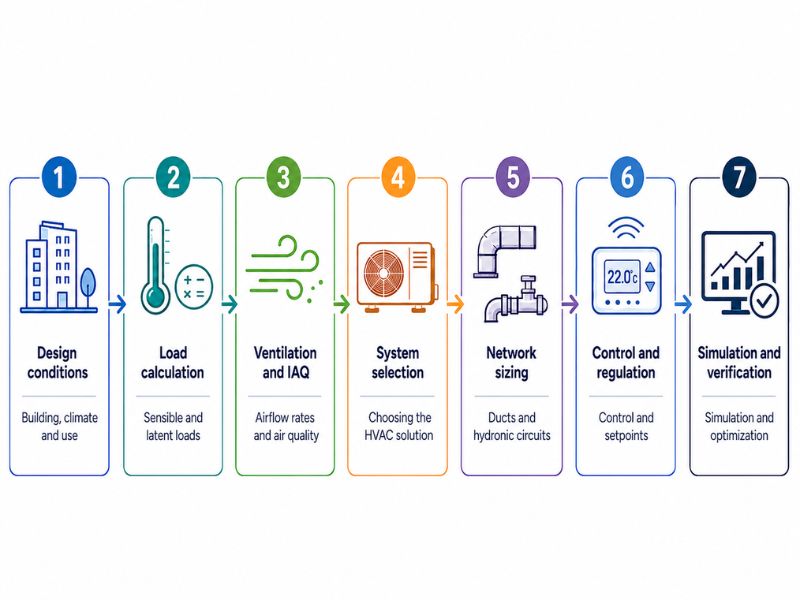
7-step HVAC process
Main Areas of Application for HVAC Design
HVAC design is applied in various building contexts, each characterized by specific requirements in terms of comfort, environmental control, and energy management. The choice of system solutions depends on the intended use of the spaces, internal loads, and the level of control required.
The main areas of application include:
- residential buildings, where the focus is on living comfort, quietness, and ease of managing the systems;
- tertiary and commercial sector, which requires flexible systems and precise adjustments according to the variable occupancy of the environments;
- industrial sector, where controlling thermo-hygrometric conditions is essential for the quality and continuity of production processes;
- healthcare facilities and controlled environments, which impose high standards for filtration, air exchanges, and safety.
In all these areas, air conditioning systems allow for an integrated management of environmental parameters, ensuring stability of internal conditions and adequate air quality based on specific operational needs.
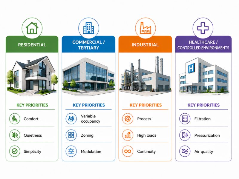
HVAC Priorities for Buildings
Examples of HVAC Design in Residential and Commercial Settings
HVAC design varies significantly between residential and commercial settings, both in scale and complexity of systems. In the residential sector, solutions aim to ensure continuous comfort and ease of management, with compact and high-efficiency systems.
Some of the most common solutions include:
- heat pumps for heating and cooling;
- radiant floor or ceiling systems;
- controlled mechanical ventilation with heat recovery.
In the commercial and office sector, however, requirements related to larger spaces, higher occupancy, and variable thermal loads throughout the day come into play. In these cases, more complex solutions are adopted, including:
- all-air systems, particularly suitable for large open spaces;
- variable air volume (VAV) systems;
- air-water systems;
- centralized systems with ducted distribution.
The design must consider the flexibility of space usage and the possibility of modulating performance based on occupancy, in order to avoid energy waste and ensure uniform environmental conditions.
HVAC Design in Controlled Environments
Controlled environments require a higher level of precision than ordinary HVAC systems because environmental conditions can directly influence processes, activities, or product quality.
Key parameters to be monitored include:
- air filtration;
- particle concentration, where applicable;
- pressure differentials;
- temperature and humidity;
- flow rates and exchanges;
- operational continuity.
Clean rooms are environments designed to maintain control over the concentration of airborne particles, temperature, humidity, pressure, and, when necessary, microbiological contamination. They are used, for example, in the pharmaceutical, healthcare, electronic, and food sectors, where air quality can affect processes or products.
The HVAC design of a clean room requires specific ventilation and filtration systems, often with high-efficiency filters, controlled air exchanges, and pressure differentials between environments. The classification of the environment depends on the concentration of particles present in the air and the requirements of the process taking place within it.
HVAC Design for Energy Efficiency and Environmental Sustainability
Sustainable HVAC design aims to reduce the energy and environmental impact of buildings through solutions that enhance efficiency without compromising indoor comfort. This approach requires a close integration between the building envelope, system, and control systems.
Some of the most effective strategies include:
- use of renewable sources, such as solar thermal and geothermal;
- heat recovery from exhaust air;
- load optimization through energy simulations;
- intelligent regulation of systems based on actual conditions;
- modulation of flow rates according to occupancy;
- optimization of operating temperatures of circuits.
A particularly effective solution is free cooling, which takes advantage of favorable external climatic conditions to reduce or, when possible, temporarily avoid mechanical cooling, resulting in decreased consumption.
Ventilation and Air Quality in HVAC Design
Ventilation is one of the fundamental elements of HVAC design because it directly influences indoor air quality, comfort, and energy consumption.
Ventilation sizing must consider:
- the intended use of the spaces;
- the number and profile of occupants;
- external air flow rates;
- any internal contaminants;
- filtration;
- energy recovery;
- methods of air distribution.
In more advanced systems, the air flow can be adapted to usage conditions through demand controlled ventilation strategies, utilizing sensors and control systems.
Sizing of HVAC Duct and Hydronic Networks
Once loads, flow rates, and system types are defined, the design enters the sizing phase of the networks that distribute air and fluids within the building.
One of the challenges of this phase is to transform design loads and flow rates into correctly sized networks, simultaneously checking diameters or sections, fluid velocities, pressure losses, and circuit balancing.
When these checks are managed separately from the system model, any design modifications may require updates and repeated checks. For this reason, it can be useful to work with HVAC design and sizing software that allows for modeling the network and directly verifying its performance. With usMEP.HVAC, you can design hydronic and duct systems, size pipes and ducts, check pressure losses and flows, and balance circuits all within the same BIM workflow.
The proper design of these networks directly impacts:
- performance;
- pressure losses;
- consumption of fans and pumps;
- noise levels;
- balancing;
- operational continuity;
- comfort in the spaces.
Designing HVAC Ducts and Air Distribution Strategies
The design of ductwork is one of the most important aspects of air duct design because it determines how air is distributed in the spaces.
The designer defines:
- the sizes of the ducts based on the required flow rates;
- the air velocity to avoid noise and turbulence issues;
- the routing of the networks to minimize pressure losses;
- the position of terminals to ensure uniform diffusion.
A correct configuration of the ducts directly affects the perceived comfort and overall efficiency of the system.
Common Challenges in HVAC Duct Design
The design of duct networks presents several challenges related to both available spaces and the architectural complexity of buildings. The most frequent issues concern coexistence with other systems and the management of acoustic performance.
The main difficulties include:
- geometric constraints in ceilings and ducts;
- interference with electrical and plumbing systems;
- control of noise levels in the ducts;
- thermal losses along distribution runs;
- the need to ensure accessibility for maintenance.
Resolving these challenges requires careful coordination among design disciplines and a definition of system pathways from the earliest design stages.
Sizing of Hydronic Networks
HVAC design often also includes hydronic circuits intended for the transport of hot or chilled water between generators, terminals, and distribution systems.
The sizing must take into account:
- water flow rates;
- pipe diameters;
- fluid velocity;
- distributed and concentrated pressure losses;
- required head;
- circulating pumps;
- regulating valves;
- balancing of circuits.
A correctly sized network ensures that the terminals receive the expected flow rates while simultaneously limiting pumping consumption.
Design Considerations for Condensate Drain Lines and Traps (P-trap)
Condensate drain lines allow for the removal of water produced by cooling and dehumidification processes. An error during the design phase can cause operational issues and inadequate hygienic conditions.
The main elements to consider are:
- slope of the pipes to facilitate drainage;
- correct sizing based on the amount of condensate;
- proper configuration of traps;
- pressure conditions at the drainage point;
- accessibility for maintenance and cleaning.
The trap must be configured consistently with the pressure conditions of the unit to allow for proper drainage of condensate.
BIM and Coordination in HVAC Design
The use of BIM in HVAC design enhances information control and coordination among the various involved disciplines.
The digital model allows the designer to verify available spaces for networks, equipment, and terminals, identify possible interferences in advance, and keep information coordinated among the different disciplines.
BIM can also be linked to calculation and simulation tools, creating continuity between the geometric model and verification or sizing activities.
To delve into MEP systems modeling, IFC interoperability, and the representation of HVAC objects in the informational model, you can consult the dedicated guide to HVAC systems and BIM design.
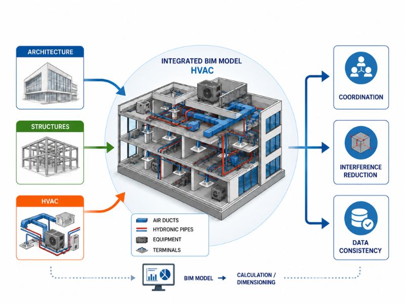
BIM HVAC Integration
Regulation, BACS and Building Automation in HVAC Systems
Building automation systems allow for the control and coordination of the operation of HVAC systems based on the actual conditions of the building.
Through sensors, controllers, and supervisory systems, it is possible to manage:
- temperatures and setpoints;
- operating times;
- flows;
- air quality;
- zone operation;
- generators;
- pumps and fans;
- energy optimization strategies.
Regulation allows for the adaptation of the system to the actual demands of the environments, preventing the systems from operating constantly at maximum power conditions.
Verification, Balancing, and Commissioning of HVAC Systems
Design does not end with the theoretical sizing of the system. Before commissioning, it is necessary to verify that the completed system operates according to the performance expected from the project.
Activities may include:
- verification of air and water flows;
- network balancing;
- control of setpoints;
- verification of the operation of control systems;
- functional tests of equipment;
- control of coherence between the project and the implemented system.
Commissioning allows for the identification of any differences between expected performance and actual system behavior, enabling interventions before regular operation begins.
Technical Skills of the HVAC Designer
The HVAC designer must possess specific skills that allow them to translate the building’s needs into correctly sized plant choices, networks, and control systems.
Among the most relevant skills are:
- thermodynamics and heat transfer;
- psychrometrics;
- fluid mechanics;
- aerodynamics design;
- hydronic design;
- calculation of thermal loads;
- ventilation and air quality;
- energy and plant regulations;
- BIM and interdisciplinary coordination;
- energy simulation;
- automation and control systems.
What Tools Are Needed for HVAC Design?
HVAC design requires various tools depending on the phase of the process.
A delicate step of the HVAC workflow is the transfer of information from energy analysis to system design. Sensitive and latent loads, ventilation flows, and thermo-hygrometric data must indeed become input data for the sizing of terminals, ducts, and piping.
Manually managing this transition can lead to data input duplications and complicate the maintenance of alignment between the energy model and the system project.
An integrated workflow allows for the direct use of the results of energy analysis in the subsequent design activities.
| Design Phase | Tool / Function |
| Building Analysis | Energy model and geometric data |
| Load Calculation | Energy calculation software |
| Dynamic Analysis | Energy simulation software |
| System Modeling | BIM/MEP Tools |
| Air Networks | Software for duct sizing, flows, and pressure losses |
| Hydronic Networks | Software for diameters, flows, heads, and balancing |
| Coordination | BIM environment and clash detection |
| Verification | Calculation tools, diagnostics, and solution comparison |
The integration between these tools allows for maintaining continuity between energy analysis, system sizing, and project coordination.
What features should HVAC design software have?
The choice of software for HVAC design and simulation depends on the level of complexity of the project and the type of analysis required. There is no one-size-fits-all solution, but a selection based on the features necessary for the design process.
The main evaluation criteria include:
- 3D modeling capability, with import from CAD and BIM;
- integrated management of energy and plant data;
- ability to perform dynamic simulations of the building’s behavior;
- reliability of calculation results and level of detail in the analyses.
To analyze the building’s energy behavior over time and compare different design scenarios, it is possible to use an energy simulation tool. When transitioning from energy analysis to the actual sizing of the system, the critical issue lies in converting loads and flows into properly sized ducts and pipes, while simultaneously checking speeds, pressure drops, and network balancing. At this stage, using a specific software for HVAC and MEP design and sizing allows for the management of modeling, calculation, and verification of networks within a single design workflow.
FAQ – HVAC Design
What does HVAC mean?
HVAC stands for Heating, Ventilation, and Air Conditioning and identifies the systems used to manage heating, ventilation, and air conditioning within buildings.
How is an HVAC system designed?
The design of an HVAC system starts with defining the internal and external conditions, continues with the calculation of thermal loads and ventilation flows, and includes the selection of the system, sizing of the networks, regulation, and final performance verification.
What data is needed to size an HVAC system?
Among the main necessary data are building and envelope characteristics, climatic conditions, intended use, occupancy, internal gains, design temperatures and humidity, thermal loads, and ventilation requirements.
How are HVAC system networks sized?
Sizing starts from the required flow rates and considers cross sections or diameters, fluid velocities, pressure drops, available head, and balancing. For air distribution networks, it is also necessary to verify air distribution and acoustic conditions; for water-based systems, pumps, valves, and flow rates to the terminals must be checked.
What is the role of BIM in HVAC design?
BIM allows for the geometric and informational coordination of HVAC systems with architecture and structures, reducing interference and facilitating data exchange with calculation and sizing tools.
What is the purpose of commissioning an HVAC system?
Commissioning allows for verifying that the installed system operates consistently with the performance specified in the project by checking flow rates, balancing, adjustment, and the operation of equipment.


