
Schematic Design Architecture: What Is It and How It Works
Schematic design defines the initial project choices. Discover how it works, what documents it includes, and the differences with concept and design development.
IN SHORT:
Schematic design is the phase in which the brief, constraints, and requirements of the client are transformed into a preliminary and verifiable architectural solution. It mainly defines the distribution of spaces, functional relationships, volumetry, site relationship, and initial technical and economic strategies. Among the most common deliverables are site plans, floor plans, sections, elevations, diagrams, 3D models, and preliminary cost estimates. The decisions made in schematic design form the basis for the development of the entire project.
How do we transition from the initial project ideas to a solution that meets the client’s needs and the constraints of the intervention?
The answer is quite simple: through schematic design, the phase where spaces, volumes, functions, and relationships between the environments begin to define the project layout. The designer focuses on the main characteristics of the work and verifies its consistency with respect to needs, constraints, costs, and performance.
The initial project choices are translated into a series of documents, including floor plans, sections, diagrams, and volumetric studies, which allow for the analysis and comparison of different hypotheses. A 3D/BIM building design software allows you to develop design alternatives in a three-dimensional BIM model, useful for visualizing the spaces and quickly evaluating the consequences of the choices made. The same model can also be used in subsequent phases, up to the definition of more detailed aspects.
The decisions made in the schematic design phase form the basis for the development of the entire project. Therefore, discover how schematic design works, what documents it includes, and which figures participate in the process.
Contents
- What is schematic design?
- Where schematic design architecture fits in the design process
- Input: what information is needed before starting
- The schematic design process step by step
- What documents are included in the schematic design?
- How detailed should schematic designs be?
- Schematic design in architecture and interior design
- Concept design vs schematic design
- Schematic design vs design development
- Who participates in schematic design?
- Tools for Schematic Design Architecture
- How to Present a Schematic Design to the Client
- Practical Example of Schematic Design Architecture
- FAQ – Schematic design architecture
What is schematic design?
Schematic design is a phase of the design process in which the needs of the client are transformed into one or more defined architectural solutions.
The objective is to define the overall structure of the project before moving on to technical and construction development. In this phase, the designer establishes, with a still preliminary level of detail, how to organize the spaces, what relationships to create between the different functions, what shape to give to the building, and how to place it on the site.
Schematic design is widely used in international professional practice. The American Institute of Architects (AIA) considers it one of the main phases of design services. During this phase, the architect typically develops drawings, documents, or other representation tools capable of describing design concepts, spatial relationships, scale, and form of the building, also addressing the main urban and territorial conditions and a preliminary cost assessment.
However, the actual documents required are not universal: they depend on the contract, the type of intervention, and the level of detail agreed upon between the client and the designer.
The result of the schematic design is therefore not a project ready for construction. It is a sufficiently defined design solution to allow the team and the client to make informed decisions.
Schematic design mainly answers questions such as:
- what functions should the building host?
- how should the environments be organized?
- what paths should users, staff, and materials follow?
- what are the main accesses?
- what relationship should the building have with the lot?
- what volumetry best responds to the project goals?
- what are the main technical and regulatory constraints?
- what order of magnitude of costs does each solution entail?
Schematic design is a phase, not a single drawing
Schematic design does not coincide with a single board.
A floor plan, for example, can describe the distribution of spaces, but it is not sufficient to understand the relationship of the building with the site, its volumetry, flows, orientation, or the main economic consequences of the design choices.
Schematic design therefore includes a coordinated set of documents, analysis, and decisions. This package may include floor plans, sections, elevations, site plans, functional diagrams, volumetric studies, 3D models, reference images, reports, and preliminary cost estimates.
The value of the phase depends on the consistency between these elements. If the plan shows a specific organization of spaces, for example, then the volumetry, sections, and initial plant indications must also be compatible with that choice.
Where schematic design architecture fits in the design process
In the typical sequence adopted in many international contexts, schematic design architecture is positioned after the initial definition of goals and before the detailed development of the project.
In many design workflows, a simplified sequence may be:
brief and pre-design → concept design → schematic design architecture → design development → technical documentation and construction documentation → construction
The sequence can change based on the method adopted, the contract, and the nature of the intervention.
However, the principle remains the same: first, needs, requirements, and constraints are clarified, then a solution is defined, and finally, it is developed with an increasing level of detail.
| Phase | Main Objective | Typical Contents | Level of Definition |
| Concept design | Define the guiding idea | Concept, diagrams, references, initial spatial and volumetric hypotheses | Initial |
| Schematic design architecture | Transform the idea into a verifiable solution | Layout, plans, sections, volumetry, flows, initial technical strategies, and costs | Preliminary but verifiable |
| Design development | Develop and coordinate the approved solution | Materials, construction systems, structures, systems, envelope, and components | Advanced |
| Construction documentation | Precisely describe what needs to be built | Drawings, specifications, and details necessary for subsequent activities | High |
Activities before schematic design architecture
Before developing the first schematic plans, it is necessary to collect project information.
The team must know at least the functional program, site characteristics, planning and regulatory constraints, the available budget, and the main expectations of the client.
Surveys, analysis of the existing building, feasibility studies, preliminary investigations, and specialized assessments may also be necessary.
The outcome of the initial activities should be a reference framework sufficiently clear to allow the designer to formulate alternatives.
Phases following schematic design architecture
After the approval of the schematic design architecture, the project moves to a phase of greater definition.
In design development, for example, construction systems, materials, structures, systems, envelope, openings, and other elements that remain at a preliminary level in schematic design architecture are explored in depth.
Subsequently, the documentation progressively reaches the necessary level for authorizations, contracts, construction, and coordination of works, according to the design process and the contractual framework adopted.
Each step should increase the level of information without arbitrarily modifying previously approved fundamental decisions.
The approval “gate”
The conclusion of the schematic design architecture should coincide with a precise moment of approval.
The client must be able to verify the proposed solution, understand its advantages and critical issues, and decide whether to authorize the transition to the next phase.
It is useful to prepare a decision log, that is, a record of decisions, with:
- approved solution;
- analyzed alternatives;
- reasons for the choice;
- preliminary costs;
- main constraints;
- requested changes;
- outstanding issues.
In projects where timelines are a critical factor, the gate may also include a preliminary schedule verification to identify any consequences of design choices on subsequent phases.
This step reduces the risk that decisions already made may be called into question without clear justification in the following phases.

Schematic design architecture
Input: what information is needed before starting
Before developing the initial design alternatives, it is essential to gather information that defines the goals, constraints, and conditions of the project. The schematic design, in fact, starts from a framework that includes the client’s needs, the characteristics of the site, the budget, the timing, and the regulatory and performance requirements.
In addition to these elements, the client’s qualitative expectations are added, such as the image of the building, the flexibility of spaces, the quality of natural light, and the relationship with the context.
Not all data needs to be definitive, but it is important to distinguish certain information from hypotheses yet to be verified. The initial framework allows for the evaluation of alternatives and identification of aspects that require further investigation.
The definition of this framework therefore requires the analysis of the main inputs that can influence design choices.
Brief and functional program
The brief collects the client’s objectives. The functional program translates them into rooms, areas, relationships, and requirements.
For each space, it is useful to indicate function, indicative area, number of users, specific requirements, and relationship with other environments.
A program for a school, for example, must include classrooms, laboratories, services, administrative areas, common areas, and pathways, in addition to defining the main relationships between these functions.
Site and context
The site provides crucial information for the design solution.
It is necessary to analyze orientation, access, topography, existing buildings, sightlines, solar exposure, noise, vegetation, infrastructure, and characteristics of the urban fabric.
For a renovation, the analysis must also include the condition of the existing building and the constraints that may affect distribution, structure, and systems.
Budget and timing
The budget must be integrated into the process from the very first alternatives.
The preliminary estimate can be based on areas, volumes, parametric costs, and hypothesized qualitative characteristics. It does not have the precision of a detailed quantity survey but allows for understanding whether a solution is compatible with the available resources.
Timing also influences the choices. A project with tight deadlines may require a different strategy compared to an intervention for which the team has more time for analysis and development activities.
Regulatory and performance
Among the inputs are the main urban planning, building, fire safety, energy, accessibility, and safety requirements.
Not all checks need to be completed at this stage. However, constraints that can modify the solution should emerge immediately.
A height limit, a minimum distance from the boundary, or an accessibility requirement can substantially alter a floor plan or a volumetric design.
Client’s identity and expectations
The brief should also encompass the qualitative aspects.
The client may have specific expectations regarding the image of the building, the flexibility of the spaces, the materials, the brightness, the relationship with the context, or the level of representativeness.
Transforming these expectations into verifiable criteria allows for comparing the alternatives with greater objectivity.
The schematic design process step by step
The schematic design follows an iterative process where each decision arises from the information collected in the previous phases and produces data useful for subsequent checks. The path is not always perfectly linear, as a structural verification may necessitate a modification of the layout, a light simulation may lead to changing the orientation, and an update of costs may require a new alternative.
Therefore, the schematic design must maintain a certain degree of flexibility. The project must evolve without losing control over decisions already made, the client’s requirements, and the budget.
1. Analyze brief, site, and constraints
The first step consists of organizing the available information.
It is useful to define mandatory requirements, client preferences, regulatory constraints, data to verify, and design assumptions. A requirements matrix allows the team to understand which elements have the greatest influence on subsequent choices.
2. Organize functions, flows, and adjacencies
The designer determines which environments need to be close together and which should remain separate.
Bubble diagrams, adjacency diagrams, and flow diagrams enable the testing of different configurations before developing a detailed plan.
These tools are particularly useful for complex buildings, such as hospitals, schools, hotels, and production facilities.
3. Generate multiple design alternatives
Schematic design should allow, when the size and characteristics of the assignment make it appropriate, for the comparison between multiple solutions.
The alternatives may differ in orientation, volume position, internal distribution, access points, service organization, or the relationship between served spaces and support spaces.
Developing and evaluating alternatives in the early stage generally allows for interventions before the project reaches a level of detail that would make changes more complex.
4. Define layout, scale, and volumetry
The alternatives are transformed into plans, sections, and three-dimensional models.
The designer checks indicative dimensions, proportions, heights, clearances, and the ratio of solid to void spaces. The volumetry must be consistent with the internal distribution and the characteristics of the lot.
5. Verify light, orientation, access, and performance
At this point, the first checks on performance come into play.
The orientation can affect natural light and the control of solar gains. The position of the access points determines the flows. The distribution of openings can impact comfort, energy efficiency, and the relationship with the outside.
Preliminary analyses of lighting, energy, or acoustics may also alter the solution.
6. Involve structures, systems, and consultants
In projects where they affect the feasibility of the solution, structures and systems should be considered during the schematic design phase with a level of detail proportionate to the complexity of the intervention.
The structural engineer can verify the compatibility between the structural grid and architectural distribution. MEP consultants can identify technical rooms, shafts, main pathways, and spaces required for the systems.
An early involvement of disciplines that most influence the building’s configuration can reduce the risk of significant changes in later phases.
7. Compare options with measurable criteria
The alternatives can be compared through a matrix with indicators such as:
- net area;
- gross area;
- preliminary cost;
- distribution efficiency;
- quality of natural lighting;
- flexibility;
- construction complexity;
- energy performance;
- quality of outdoor spaces;
- compatibility with the timeline.
The comparison thus becomes more transparent and less dependent on personal preferences alone.
8. Present proposals to the client
The presentation must explain the path that led to the solutions.
An effective sequence includes objectives, constraints, alternatives, comparison criteria, recommended solution, and main economic consequences.
Plans, sections, and 3D views must have complementary roles. The render shows the atmosphere and appearance of the proposal, the plan explains the distribution, while the section clarifies the vertical relationships.
9. Gather feedback and revise
Client feedback must translate into precise modifications.
It is useful to distinguish requests arising from functional needs, aesthetic preferences, and changes that entail consequences on budget or time.
This distinction allows for evaluating each revision before incorporating it into the project.
10. Approve and document the solution
The final activity consists of formalizing the chosen solution.
The approved package must contain the deliverables specified by the assignment, the main economic evaluations, and technical assessments and documentation of the decisions made.
The decision log can be updated at this time to indicate the approved solution, any outstanding conditions, and the aspects to be deepened in the next phase.
In this way, the team has a shared basis for moving on to design development.

The schematic design process
What documents are included in the schematic design?
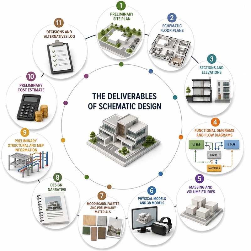
The typical documents of schematic design can include site plans, floor plans, sections, elevations, functional diagrams and flow charts, volumetric studies, 3D models, explanatory reports, preliminary indications on structures and systems, and cost estimates.
There is no identical package for every intervention. The documents depend on the contract, the size, and the complexity of the work, and especially on the decisions that need to be made at the end of the phase.
| Document | What it represents | Which decision it supports |
| Site plan | Building, lot, accesses, and outdoor spaces | Location and relationship with the context |
| Schematic plan | Functions, areas, paths, and relationships | Space distribution |
| Section | Heights, levels, and vertical relationships | Volumetric organization |
| Elevation | Proportions, openings, and general character | Configuration of the envelope |
| Diagrams | Adjacencies and flows | Functional organization |
| Volumetric study | Shape, mass, orientation | Volume-site relationship |
| 3D/BIM model | Coordinated geometry and essential information | Overall solution verification |
| Preliminary estimate | Magnitude of costs | Compatibility with the budget |
| Decision log | Alternatives and decisions made | Process traceability |
Preliminary site plan
The site plan (general plan) places the project within the lot and clarifies its relationship with the context.
It can show the outline of the building, pedestrian and vehicular accesses, parking, paths, green spaces, service areas, and major existing elements.
The drawing allows verification of one of the first decisions of the schematic design, namely where to place the building and how to connect it to the external space system.
In an urban project, it can also show the relationship with streets, adjacent buildings, and public spaces.
Schematic plans
The plans are one of the main documents.
They must show the distribution of functions, indicative dimensions, main paths, accesses, service cores, and relationships between environments.
The level of detail must remain consistent with the phase. It is not necessary to indicate every construction component, but the spatial configuration must be sufficiently clear to allow for an evaluation of the project.
The plans can be accompanied by areas and quantitative data, useful for comparing alternatives.
Sections and elevations
Sections allow verification of what the plan cannot show, namely heights, levels, relationships between floors, double-height spaces, vertical connections, and relationship with the ground.
Elevations, on the other hand, define the general character of the building. They can show openings, proportions, solid and void areas, indicative materials, and the relationship between different parts of the facade.
At this stage, it is not necessary to achieve a complete definition of the envelope, but the solution must be sufficiently clear to allow for an evaluation of its architectural expression.
Functional and flow diagrams
Diagrams represent relationships that a traditional architectural drawing may render less immediate.
A functional diagram can show, for example, which environments need to be adjacent. A flow diagram can distinguish between user paths and those of staff or materials.
These tools are particularly important in buildings with high functional complexity.
Volumetric studies and massing
Volumetric studies, or massing studies, are used to verify the overall shape of the building.
They can be created through simple three-dimensional models, axonometrics, or perspective views. The objective is to evaluate footprint, height, proportions, orientation, and relationship with the context.
A series of volumetric studies can also show how the project changes based on the position of the volume on the lot or its articulation.
Physical models and 3D models
The physical model allows for an immediate reading of the volumetry and the relationships with the site. The digital model, on the other hand, offers greater speed in modifying alternatives and producing views and sections.
The use of virtual and augmented reality can add an additional level of understanding, allowing the client to explore the spaces and more easily assess proportions and relationships between environments.
In BIM, the model can also contain non-geometric information, but the informational content must be proportionate to the goals of the phase.
The schematic design model should therefore not be developed prematurely as a complete construction model: unnecessary information would increase the modeling and revision workload without improving the quality of decisions.
Mood board, palettes, and preliminary materiality
In architectural design, and especially in interior design, the perceptual component can have significant weight.
Mood boards, color palettes, and material references help to define the identity of the project. They can contain reference images, textures, colors, materials, and indicative detail solutions.
These tools do not equate to a definitive specification of materials. Rather, they serve to establish a design direction that can be explored further in later phases.
Illustrative report
The illustrative report collects and explains the main choices of the schematic design.
It can describe the relationship with the site, functional organization, distribution criteria, analyzed alternatives, the chosen solution, and the main verifications carried out.
A good report should also assist those who did not participate in project meetings to understand the logic of the solution.
Preliminary indications on structures and systems
Structures and systems do not need to be developed at the same level as the execution phase, but they must be represented in their main characteristics.
For structures, load-bearing grids, the position of main vertical elements, indicative spans, and hypothesized structural systems may be indicated.
For systems, technical rooms, service shafts, risers, central systems, and main pathways can be identified.
This information allows for verification that the space designated for technical components is compatible with the architectural solution.
Preliminary cost estimate
The preliminary estimate connects the project to the available financial resources.
The evaluation can be based on volumes, parametric costs, or key quantities. Its purpose is not to replace a detailed bill of quantities but to indicate the magnitude of the investment and allow for a comparison between alternatives.
If a solution significantly exceeds the budget, the issue must arise before proceeding to the next phase.
Record of decisions and alternatives
The record of decisions documents the design process.
It can report the date of the decision, the topic discussed, the alternatives considered, the choice made, the motivations, and any effects on costs, time, or performance.
This document takes on particular value in complex projects, where many decisions are made by different parties.
The record allows for reconstructing the reasons for a choice even months later and reduces the risk of reopening issues that have already been resolved without new elements.
The deliverables of schematic design
How detailed should schematic designs be?
The level of detail must be sufficient to make decisions, but it should not anticipate the level of definition of the construction documentation.
A schematic plan should clarify distribution, functions, pathways, and indicative dimensions. It does not necessarily have to contain every stratigraphy, detail of nodes, product specifications, or executive indications.
A good criterion is to ask oneself if a particular piece of information is needed to verify a decision.
If the answer is negative, that information probably belongs to a later phase.
Schematic design in architecture and interior design
In architecture, schematic design mainly concerns site, volume, distribution, orientation, envelope, and the relationship between internal and external spaces.
In interior design, the focus is more on layout, pathways, furniture, lighting, materials, colors, and atmosphere. A proper management of the interior design project allows for coordinating these choices and keeping them consistent with the goals defined in the schematic design phase.
The method remains similar: in both cases, requirements, alternatives, and selection criteria are defined before developing the detailed documentation.
For a hotel, for example, the schematic design can define the relationship between rooms, reception, dining, and common areas. For an office, it can establish the distribution of workstations, meeting rooms, and support areas.
Concept design vs schematic design
The main difference between concept design and schematic design concerns the level of definition: the concept design identifies the guiding idea of the project, while the schematic design verifies how that idea can become a spatial, technical, and economically viable solution.
The concept can relate to form, the relationship with the context, spatial organization, atmosphere, or an architectural principle. Schematic design brings this idea to a more concrete and verifiable level. It introduces layouts, indicative dimensions, flows, volume, performance, and preliminary costs.
A simple distinction is as follows:
- concept design: what guiding idea drives the project?
- schematic design: how can that idea become a verifiable spatial solution?
The two activities can overlap, and not all professional systems organize them as independent contractual phases.
Schematic design vs design development
The main difference is that schematic design defines the overall configuration of the project, while design development develops and coordinates with greater precision the already approved solution.
In design development, the level of detail and coordination between architecture, structures, and systems increases. Materials, construction systems, openings, components, and plant distributions are explored further, reaching the level of definition necessary for subsequent design phases and for the development of executive drawings.
The transition should therefore lead from an approved solution to a more defined project, not unnecessarily reopening all previous decisions.
Who participates in schematic design?
Schematic design requires the contribution of different skills because the decisions made in this phase have consequences for architecture, structures, systems, costs, timelines, and performance.
The composition of the group depends on the size and complexity of the intervention. In a small residential project, the client and designer may suffice, with the support of some consultants. In a complex building, a multidisciplinary team of numerous specialists may be necessary.
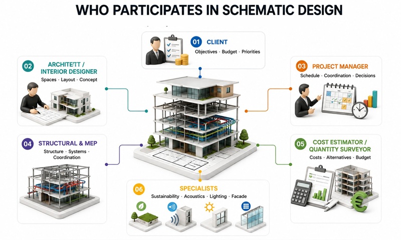
Client
The client defines the objectives of the intervention, the budget, the priorities, and the functional requirements.
During the schematic design, they must be able to evaluate the alternatives and make decisions that influence the project.
Their role does not consist of defining every technical choice but of providing indications on the needs of the organization, priorities, and the criteria by which to evaluate the proposals.
It is important that they receive sufficiently clear information to understand the consequences of their decisions. A request for more surface area, for example, can lead to an increase in costs, a modification of the volume, or a reduction in other functions.
Architect or interior designer
The architect or interior designer coordinates the definition of the spatial solution.
They interpret the brief, analyze the site, develop alternatives, and coordinate inputs from other professionals.
Their task also includes verifying the consistency between the various representations of the project: plan, section, elevations, 3D model, and report must describe the same solution.
In the case of interior design, the professional focuses a larger part of the work on layout, furniture, materials, lighting, colors, and the perceptual quality of the environments.
Project manager
The project manager coordinates the process from an organizational perspective.
They establish tasks, responsibilities, deadlines, and review moments. They also coordinate exchanges between the client, designers, and consultants.
During the schematic design process, they can manage the meeting calendar, the flow of information, and the approval process for alternatives.
Their role becomes particularly important when the number of involved parties increases.
Structural engineer and MEP consultants
The structural engineer checks the compatibility between the load-bearing system and the architectural organization.
They can indicate an initial structural grid, the position of the main load-bearing elements, and plausible spans. This information can directly influence the distribution of spaces and the shape of the building.
The MEP consultants, which stands for Mechanical, Electrical, and Plumbing, take care of the main strategies for mechanical, electrical, and plumbing systems.
At this stage, they can identify the space requirements for technical rooms, shafts, risers, and main equipment.
The early involvement of relevant disciplines reduces the risk of technical conflicts emerging when the project has already been developed in greater detail.
Cost estimator or quantity surveyor
The cost estimator or quantity surveyor evaluates the economic impact of design choices.
Their contribution is not limited to the final estimate: they can participate in the comparison between alternatives and indicate which decisions have the greatest influence on the overall cost.
For example, a solution with a larger glazed surface may have consequences on the cost of the envelope, while a more complex distribution may increase connection areas, the number of walls, and the development of systems.
The presence of economic expertise in the early phases allows for verifying the design direction before decisions become more complex to modify.
Sustainability, acoustic, lighting, and facade specialists
Some projects require specialized skills even in the schematic design phase.
The sustainability expert can assess orientation, passive strategies, energy consumption, and main environmental objectives.
The acoustic consultant can check the distribution of functions, the position of noisy areas, and insulation needs.
The lighting specialist can analyze natural and artificial lighting, while the facade consultant can verify the consequences of volumetric and opening choices on the envelope system.
The principle is simple: a competence must enter the process before the moment when their decisions become difficult to integrate.
Not all these specialists necessarily need to participate in every meeting. Their involvement should be proportionate to the complexity of the project and the issues that may affect its feasibility.
Who participates in schematic design
Tools for Schematic Design Architecture
The tools depend on the complexity of the project.
Among the most commonly used are:
- sketches and diagrams;
- 2D CAD;
- BIM software;
- 3D modeling;
- rendering tools;
- spreadsheets for surfaces and costs;
- software for energy analysis;
- tools for lighting analysis;
- platforms for data coordination and sharing.
BIM can play an important role because it allows linking geometry and information. Even at this stage, however, the model must contain a level of information consistent with the objectives of the schematic design architecture.
Inserting unnecessary details too early can increase review work without improving the quality of decisions.
How to Present a Schematic Design to the Client
The presentation must allow the client to understand what has been decided, which alternatives have been evaluated, and why one solution has been preferred over others. It is therefore important to present the architectural project through a clear synthesis of the choices made and the information necessary for evaluation.
An effective structure may include:
- project objectives;
- characteristics and constraints of the site;
- functional program;
- developed alternatives;
- comparison criteria;
- recommended solution;
- plans, sections, and 3D views;
- preliminary costs;
- main implications on timing;
- open critical issues;
- decisions required from the client.
It is preferable not to entrust the presentation solely to renders.
A photorealistic image can effectively communicate atmosphere, materials, and volume, but it does not allow for assessing distribution, flows, surfaces, or costs on its own.
The presentation must therefore combine visual representation and measurable information.
Practical Example of Schematic Design Architecture
Consider the project of an office building of about 1,500 m², intended for 80 workstations, with meeting rooms, reception, break area, and service spaces.
The client establishes three priorities:
- flexibility of spaces;
- good availability of natural light;
- compliance with a predetermined budget.
The first analysis concerns the lot, access points, orientation, views, and conditions of the context. The team also defines the functional program and indicative surfaces.
At this point, three alternatives are developed:
- solution A includes a central core with services and distribution, while offices extend along the perimeter;
- solution B uses a central distribution spine with groups of offices on either side;
- solution C concentrates meeting rooms and services in a lateral band and leaves a large flexible central space for workstations.
The three options are compared based on usable area, length of paths, access to natural light, flexibility, plant complexity, and preliminary cost.
Solution A ensures compact distribution but offers less freedom for future transformations. Solution B organizes flows well, but requires a more articulated distribution network. Solution C offers greater flexibility but requires particular attention to acoustics and plant distribution.
The client chooses solution C.
The team then proceeds with a more precise schematic plan, a section, a volumetric study, a preliminary hypothesis for the placement of technical rooms, and a preliminary scheme of the plants.
The cost estimate is updated based on the surfaces and main characteristics of the solution.
It is also verified that the solution does not introduce conditions that are incompatible with the main deadlines set by the project program.
The final package includes plans, sections, 3D views, an illustrative report, preliminary estimate, comparison between alternatives, and a record of decisions.
The client approves the solution and authorizes moving to the next phase.
The example demonstrates the main function of schematic design architecture, which is to reduce uncertainty before investing time and resources in the detailed development of the project. Schematic design allows to verify in advance if a solution meets the functional, spatial, technical, and economic needs of the intervention.
When the process concludes with a documented decision, the team has a more solid foundation to tackle the subsequent stages of design, even with the support of a 3D/BIM design software that enables the development and coordination of the model, the documents, and the project information.
FAQ – Schematic design architecture
What does a schematic design include?
The schematic design can include site plans, schematic floor plans, sections, elevations, functional and flow diagrams, volumetric studies, 3D models, preliminary indications on structures and systems, illustrative reports, and initial cost estimates. The actual documents depend on the contract and the complexity of the intervention.
What is the difference between concept design and schematic design?
The concept design primarily defines the guiding idea of the project. The schematic design translates this idea into a more concrete and verifiable solution through layouts, dimensions, volumetry, flows, and initial technical and economic assessments.
What is the difference between schematic design and design development?
The schematic design establishes the overall setup of the project. The design development further explores and coordinates the approved solution by defining materials, structures, systems, enclosures, and components more precisely.
How detailed should a schematic design be?
It should contain sufficient information to evaluate and approve the fundamental decisions of the project without unnecessarily anticipating the level of detail of the subsequent technical and construction phases.
Who approves the schematic design?
Normally, the solution is submitted to the client, who verifies compliance with the objectives, evaluates alternatives, and authorizes the transition to the next phase according to what is provided by the contract and the adopted design process.


